Integrated BIM, MEPF & VDC Engineering
STRUCTURAL STEEL • CONNECTIONS • FABRICATION DETAILING

Steel Connection Detailing Services

Translate supplied structural connection design information into coordinated fabrication and erection documentation — covering beam connections, bracing, base plates, splices, anchors, plates, bolts, weld references and steel member interfaces.

Beam Connections Brace Connections Base Plates Splices Anchor Layouts Fabrication Coordination
Review Engineering Design
Detail Connection Geometry
Coordinate Fabrication Interfaces
Issue Shop Drawings
Structural Steel Connections

Make Approved Connection Information Fabrication-Ready

Structural drawings may define framing geometry and connection intent, while downstream fabrication requires more detailed component information.

Connection detailing organizes supplied engineering information into plates, bolt locations, weld references, member interfaces, dimensions and fabrication details.

The detailing process should maintain a clear distinction between documenting an approved connection and engineering the connection itself.
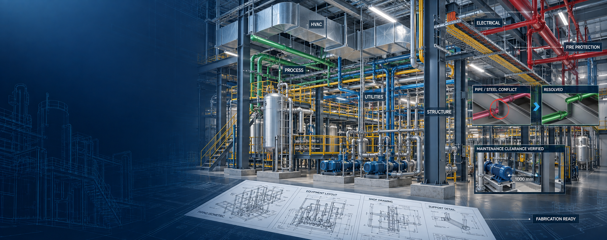
Structural steel connection detailing services
Connection Design → Detailing → Coordination → Fabrication Documentation Structured documentation from approved engineering information.
Connection Detailing Capabilities

Detailed Documentation Across Structural Steel Interfaces

Connection detailing can be developed from supplied structural drawings, engineer-designed connections, approved sketches, design criteria and project specifications.

01 / BEAM-COLUMN

Beam-to-Column Connections

Detail approved beam-to-column connection conditions and member interfaces.

02 / BEAM-BEAM

Beam-to-Beam Connections

Develop fabrication details for supplied beam-to-beam connection arrangements.

03 / BRACING

Bracing Connections

Detail approved brace, gusset and associated framing interfaces.

04 / BASE PLATES

Base Plate Detailing

Document approved base plates, column interfaces and anchor information.

05 / SPLICES

Member Splice Detailing

Prepare shop drawings for approved column, beam or other member splice conditions.

06 / ANCHORS

Anchor Layout Documentation

Document supplied anchor locations, patterns and project references.

07 / PLATES

Plate Detailing

Prepare fabrication information for approved plates, stiffeners and connection components.

08 / BOLTS & WELDS

Bolt & Weld Information

Document supplied bolt and weld requirements within fabrication drawings.

09 / COORDINATION

Fabrication Coordination

Coordinate connection geometry with member fabrication and erection information.

Typical Connection Conditions

Connection Detailing Across Steel Framing Interfaces

TYPE 01 Shear Connections Document approved project-defined shear connection information.
TYPE 02 Moment Connections Detail engineer-designed moment connection configurations where supplied.
TYPE 03 Brace Connections Document supplied brace, gusset and framing interfaces.
TYPE 04 Column Splices Detail approved column splice plate and fastening information.
TYPE 05 Beam Splices Document engineer-defined beam splice connection information.
TYPE 06 Base Connections Detail approved column base and foundation-interface information.
TYPE 07 Truss Interfaces Document supplied project-defined truss connection conditions.
TYPE 08 Miscellaneous Interfaces Detail approved steel interfaces beyond primary framing where included.
Detailing vs Engineering

A Detailed Connection Is Not Automatically a Designed Connection

A fabrication drawing may show plates, bolts, weld references and exact member interfaces.

That level of detail does not itself establish structural adequacy or replace engineering calculations.

Connection Design Defines structural requirements, forces and approved connection behavior.
Connection Detailing Converts approved engineering information into fabrication documentation.
Fabrication Coordination Aligns connection geometry with members, holes, plates and project interfaces.
Engineering Approval Remains with the responsible structural or connection engineer.
Connection Detailing Workflow

From Approved Design to Fabrication-Ready Documentation

01

Review

Review structural, connection and project design information.

02

Identify

Confirm connection locations, member interfaces and scope.

03

Detail

Develop plates, bolts, weld references, holes and component geometry.

04

Coordinate

Review connections relative to adjacent framing and fabrication conditions.

05

Revise

Incorporate approved review comments and updated information.

06

Release

Prepare the agreed detailing package for fabrication or project review.

Connection Drawing Outputs

Typical Steel Connection Detailing Deliverables

Connection Shop Drawings

Detailed views showing approved connection geometry, components and member interfaces.

Beam Connection Details

Document supplied beam-to-column and beam-to-beam connection information.

Brace & Gusset Details

Prepare shop drawing information for approved brace and gusset conditions.

Base Plate Details

Document approved plate geometry, column interface and anchor references.

Splice Details

Show approved member splice geometry and fastening information.

Anchor Layouts

Prepare layouts based on supplied anchor and base information.

Connection Schedules

Organize project-defined connection references and related drawing information.

Revision Packages

Incorporate approved connection changes, redlines and review comments.

Fabrication Information

Connection Information That Supports Fabrication Review

DATA 01 Plate Geometry Project-defined plate dimensions and configuration.
DATA 02 Bolt Information Supplied bolt size, quantity and arrangement.
DATA 03 Hole Information Document project-defined hole size, pattern and location.
DATA 04 Weld References Show supplied weld type and project-defined welding information.
DATA 05 Member Orientation Clarify framing and connection member relationships.
DATA 06 Edge Distances Document approved connection geometry and supplied dimensions.
DATA 07 Connection Reference Link details to project-defined connection types and schedules.
DATA 08 Revision Information Maintain current connection revision and drawing status.
Connection Coordination

Review Connections Within the Full Steel Assembly

Connection + Member Geometry Review plates, bolts and other supplied components against framing geometry.
Connection + Adjacent Steel Check project-defined clearances around nearby steel members.
Connection + Concrete Coordinate base plates, anchors and structural concrete interfaces.
Connection + Bracing Review brace and gusset conditions within the framing assembly.
Connection + Erection Maintain connection references within erection and assembly documentation.
Connection + Fabrication Coordinate shop detail information with fabrication drawing requirements.
Inputs & Deliverables

Approved Connection Information In. Detailed Steel Documentation Out.

Typical Inputs

  • Structural engineering drawings
  • Approved connection design
  • Connection sketches
  • Structural steel model
  • Design criteria supplied by engineer
  • Project specifications
  • Bolt / weld information
  • Anchor information
  • Approved RFIs / clarifications
  • Review comments / redlines

Typical Deliverables

  • Connection shop drawings
  • Beam connection details
  • Brace / gusset details
  • Base plate details
  • Splice details
  • Anchor layouts
  • Connection schedules
  • Plate details
  • Fabrication references
  • Revision packages
Connection Detailing QA / QC

Verify Documentation Before Fabrication Issue

Connection detailing quality depends on approved engineering information, current structural geometry, controlled revisions and clear component references.

QA should confirm that the detailed connection reflects supplied design information without introducing unapproved engineering assumptions.

Connection Reference Check each detail against the supplied connection basis.
Member Geometry Review connection relative to current framing information.
Plate Information Check supplied plate geometry and references.
Bolt / Hole Information Review supplied bolt, hole and pattern information.
Weld References Confirm supplied weld information is represented correctly.
Revision Status Confirm current approved information is being detailed.
Connection Clarification Workflow

Do Not Guess Missing Connection Information

STATUS 01 Information Available Approved connection information is available for detailing.
STATUS 02 Information Missing Required engineering or dimensional information is incomplete.
STATUS 03 Clarification Raised Missing or conflicting information is routed for project clarification.
STATUS 04 Engineer Response Responsible project party supplies the required decision or design information.
STATUS 05 Detail Updated Approved response is incorporated into the connection detail.
STATUS 06 Cross-Checked Related members and drawing references are reviewed.
STATUS 07 QA Reviewed Updated detail passes the defined detailing review.
STATUS 08 Ready for Issue Connection documentation is prepared for the next project stage.
Project Applications

Steel Connection Detailing Across Structural Projects

Commercial Buildings Structural steel framing connection documentation for commercial projects.
Industrial Facilities Connections supporting structural frames, equipment and industrial steelwork.
Data Centers Structural steel connection detailing within technically coordinated environments.
Healthcare Connection documentation supporting complex structural steel framing conditions.
Institutional Projects Structural connection shop drawings for education and institutional buildings.
Miscellaneous Steel Interfaces Connection detailing for project-defined secondary steel and related interfaces.
Scope Responsibility

Connection Detailing Does Not Automatically Include Connection Engineering

MEP Global Engineering can prepare connection shop drawings, fabrication details and coordinated steel documentation from supplied engineering information.

Structural forces, bolt sizing, weld sizing, plate thickness design, anchor design, connection calculations, fatigue or seismic design, code responsibility, professional approval and stamping remain with the responsible structural or connection engineer unless specifically included through an appropriate professional scope.

Engineer-Defined Connection Structural design provides the approved engineering basis.
Detailer-Produced Documentation Shop drawings translate that information into fabrication geometry.
Missing Information Engineering gaps should be clarified, not assumed.
Formal Approval Connection engineering and professional approval remain project-specific responsibilities.
Frequently Asked Questions

Steel Connection Detailing FAQs

What is steel connection detailing?

Steel connection detailing converts supplied structural and connection design information into fabrication and shop drawings showing project-defined member interfaces, plates, bolts, holes, weld references and dimensions.

Can beam-to-column and beam-to-beam connections be detailed?

Yes. Where approved connection information is available, beam-to-column and beam-to-beam connections can be documented for fabrication.

Can brace and gusset connections be included?

Yes. Approved brace, gusset and related member-interface information can be developed into detailed drawings.

Can base plates and anchor layouts be detailed?

Yes. Base plates and anchor layouts can be documented from suitable engineering and project information.

What happens when connection information is missing?

Missing or conflicting engineering information should be identified and routed to the responsible project professional for clarification rather than being assumed during detailing.

Does connection detailing include structural calculations?

Not automatically. Connection calculations, plate design, bolt sizing, weld sizing, anchor engineering, structural analysis, code responsibility and professional approval remain with the responsible engineer unless separately included through an appropriate engineering scope.

Structural Steel Connection Documentation

Need Steel Connection Detailing Support?

Share your structural drawings, approved connection designs, steel model, project specifications and required fabrication or shop drawing outputs.

Send Project Details WhatsApp Us
WA Discuss Your Project